Friday, July 18, 2014

Wireless ADC Measuring and CAN Controller PCB

Features

  • 57K6 RF 70cm Data transceiver.
  • 8 Channel 14(or 16) bit ADC convertor.
  • Frequency measuring input.
  • CAN-bus interface.
Data from the ADC and info of the measured frequency input is transmitted to a (RF remote) host.
Data from CAN devices connected is sent to the host.
The remote host can sent data to the CAN bus.
The remote host can sent other RF commands that will be interpreted by the onboard CPU.
This allows the local CPU to control devices on the CAN bus without intervention of the (remote) host.


Saturday, March 8, 2014

Measuring the transmit frequency.

The frequncy measuring is done by using a 12bit binary counter (74LV4040).
The output is then fed to the microcontroller section for further processing.
The input of the prescaler is driven by an LVDS line receiver.These driver provide 3V output signals and have a differential sensitivity level of around 100mV and have a 400Mhz bandwidth.
The datasheet can be found here.


Measurement Bridge : Modifications

In order to adjust the frequency response of the voltage divider the capacitive leg was splitted into 2 dividers.
The first is formed by C2 and C1 + C32. The secondary divider is formed by C30 and C3.
This construction makes it easier to use a low capacitance trimmer in adjusting for a flat response.

To compensate for the error caused by the inductive part of R4 a small capacitor (C33) was added in parrallel with R6. 

Monday, February 3, 2014

Measuring Bridge : First Measurements

Here are some results of the initial phase measurements made.
Only the voltage divider has been adjusted by changing the capacitive dividing part.
I used 1.8Mhz as reference and the load was a 50 Ohm Dummy load.

Freq       Phase Error
1.8Mhz        0°
18.1Mhz      1°
24.9Mhz      1.65°
29.7Mhz      2.65°

These errors seem te be caused by the self inductance of the shunt resistors, and i was able to compensate this by adding some shunt capacitance to these shunt resistors.
At 30Mhz and using an estimated resistor inductance of 1nH yields an inductive impedance of 180mOhm. Since our shunt resitance is only 5 Ohm, this presents a large unwanted inductive part.

I added a variable capacitor on the current shunt side and adjusted it so that i had zero error at 29.7 Mhz and then made the next measurement.
The Magnitude adjustment was done likewise, i adjusted the trimmer on the voltage divider for the so that i had the same magnitude on 1.8 and 29.7 Mhz.

Then i did a measurement on all bands.

Measurement
  1.8Mhz 3.5Mhz 7Mhz 10Mhz 14Mhz 21Mhz 29.7Mhz
Phase Error 0 -0.48° -0.44° -0.29° -0.04° -0.22° -0.18°
Magnitude Error 0.02dB 0.04dB -0.16dB -0.2dB -0.17dB -0.11dB 0.03dB

As you can see from the above table, the remaining error is very acceptable and beyond expectation.


Here is an image from another angle showing the capacitive divider adjustment.


You can see the 3 small 1.5pF capacitors in series to create a total series capacitance of 0.5pF.
All used smd capactors are NP0//COG (Chip on glass)  These 1.5pF C's are rated for 1000V so they can be used even for high power levels.

Tuesday, December 24, 2013

Wideband Measuring Bridge for automatic antenna tuner with high dynamic range.

Introduction

(WORK IN PROGRESS)
The heart of an automatic antenna tuner is a good measuring bridge to measure phase and magnitudes of voltages and currents.
U1 provides the Magnitude difference between the Current and Voltage levels.
This means that it will indicate whether Zload > Zo or Zload < Zo.
The Phase output of U1 is not used since it can not distinguisch between capacitive or inductive loads. ( It's phase output voltage will be the same for +45° and -45)

A second AD8302 is used for measuring the Phase difference between the Current and the Voltage signals.
The 90° (or almost 90 )phase shifting is done with R1/C1, this allows us to see if the load is inductive or acting capacitive.
With these two signals a control loop can be arranged to tune the matching circuit.


Fig 1: Simplified working schematic.


The actual phase shift can be calculated with the formule:


This gives us a phase shift between 89,935° and 88,92° over the range 1.8Mhz...30Mhz.
The phase error is only 1° and can be compensated since we can calculate this using the above formula. Since the AD8302 phase output is 10mV/° .This means we will have to subtract 0.65mV@1.8Mhz to 10.8mV@30Mhz  from Vref/2 to get the correct value.

The design uses 2 AD8302 devices to measure phase and magnitude of currents and voltages.
The AD8302 is an excellent choice since it specs range from LF to 2.7 Ghz , and it measures over a 60 db range of input signals.
You can find the datasheet here.


The first one is used to measure the phase between the voltage and the current to the load.

The second one is used to measure the magnitude between the current and the voltages.
I use two devices because the ad8302 does not see the difference between leading and lagging signals.
By phase shifting one of the inputs -90° , the phase output gets centered around 900mV (Vref/2).
See the graph below:


Note that the 90 degrees will be on the other side if the secondairy of the current transformer is connected in reverse, the same will haven if ANT and TRX are swapped.

Besides these measurements, the bridge also contains a frequency pre-scaler so that a microcontroller can measure the operating frequency so it can drive look-up tables that control motors for tuning a  matching circuit.

The (first) prototype:

The bridge is constructed in a 55 * 74 *30 mm tinned RF box.

http://www.on5di.com/blog/complete.jpg
(some smd parts not yet mounted.)
 
 
Detail picture of the current tronsformer wound on a 4C65 ferrite torroid with Litz wire.
(not sure if this is really making a lot of difference compared to a solid wire.)


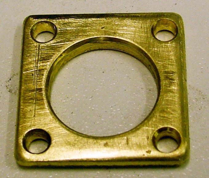
Some of the metal parts are made from brass plate and then silver plated using some (nasty) chemicals (silver cyanide and pottasium cyanide mix).
Before:


After plating :


The inner conductor is made of a piece of thick coax.(aircom plus or similar)
 
The center conductor is shielded by a piece of copper tube that has been soldered to the plated flanges. This avoids any capacitive coupling between the center conductor and the windings of the current transformer.
Here is an overview of the mechanical assembly.


My direct email